
Size Fuses or Circuit Breakers for a Solar Power System
Why and Where Do We Need A Fuse or Circuit Breaker?
When hooking up your Renogy system, the best way to add protection is by using fuses or circuit breakers. Fuses and circuit breakers are used to protect the wiring from getting too hot and protect all devices connected in the system from catching fire or getting damaged if a short circuit occurs. It is meant to protect from system over-voltage or damage from a short circuit. They are not necessary for the system to run properly, but we always recommend using fuses or circuit breakers for safety purposes.
There are three different locations that we recommend installing fuses or circuit breakers:
- Between solar panels and a charge controller
- Between a charge controller and a battery
- Between a battery and an inverter or inverter charger

Size Fuses and Circuit Breakers
The fuse or circuit breaker size varies depending on the application scenario, system capacity, and more.
- Application Scenario: The type of equipment or system being protected dictates the fuse or circuit breaker size.
- System Capacity: The overall electrical capacity of the system plays a significant role. Higher capacity systems require larger fuses or breakers to handle the larger currents safely.
- Fault Current Analysis: Assessing potential fault currents helps determine the appropriate size for fuses or breakers. This analysis ensures that they can quickly interrupt excessive currents to prevent damage or hazards.
- National Electrical Code (NEC) Compliance: Adhering to electrical codes and standards, such as those outlined in the NEC, ensures safety and regulatory compliance. These codes provide guidelines for fuse and breaker sizing based on specific scenarios and applications.
- Voltage Rating: Fuses and breakers have voltage ratings that must match the system voltage. Using the wrong voltage rating can lead to inefficient protection or even equipment damage.
- Environmental Conditions: Environmental factors like temperature and humidity can affect the performance of fuses and breakers. Sizing considerations may include derating factors to account for these conditions.
- Future Expansion: Designing for future expansion is wise. Choosing fuses or breakers with some margin allows for additional loads to be added without needing immediate upgrades.
- Manufacturer Recommendations: Consulting manufacturer specifications and recommendations is essential. They often provide detailed information on sizing criteria based on their products' capabilities and intended applications.
Between Solar Panels and A Charge Controller
A fuse between solar panels and a charge controller should be sized based on the maximum current flowing through the fuse. According to National Electrical Code (NEC), the maximum currents for solar panels should be of 1.25 times the short circuit currents of the solar panels. For fuses, circuit breakers, and other protection and isolation devices, the NEC mandates a further safety margin of 1.25 (125%), thereby having an effective overall oversizing of 156% (1.25 x 1.25) the relevant short circuit currents.
The size of a fuse or a circuit breaker between solar panels and a charge controller is dependent on two factors:
- How many solar panels you have
- How solar panels are connected (series, parallel, or series-parallel)
These two factors decide the maximum current flowing through the fuse or circuit breaker.
Series Connection
If the panels are connected in series, the voltage of each panel is added but the amperage stays the same. When selecting fuses or circuit breakers, you need to check the rated short circuit current (Isc) value for the panel you are using. The Isc is the maximum current that the solar panel can produce under any circumstances, and it determines the size of a fuse or circuit breaker for a solar panel as described in the formula below:
| Solar Panels in Series | |
|---|---|
| System Voltage* | V = V1 + V2 + ... + Vn |
| Short Circuit Current (Isc)* | Isc = I1 = I2 = ... = In |
| Rated Current of a Fuse or a Circuit Breaker | Isc of Solar Panel x 1.56 |
*In the formula, V and I represent the system voltage and short circuit current of the solar panel respectively, and 1, 2, or n represents the solar panel number respectively. For details about solar panels in series, parallel, and series-parallel, see A Guide Between Series and Parallel Connections.
Example
If you have two 100W panels connected in series, each producing 20 volts and the rated short circuit current (Isc) is 5 amps, the total output would be 40 volts at a short circuit current of 5 amps.
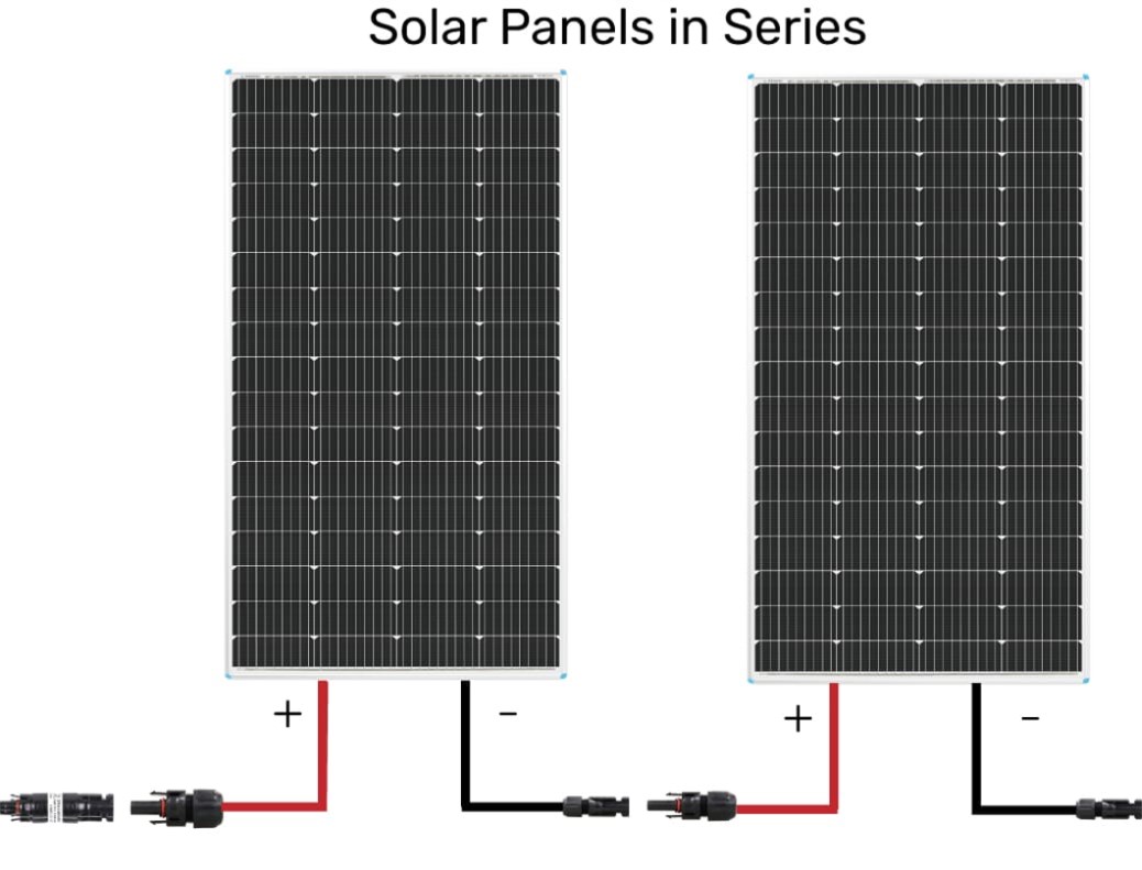
We should multiply Isc by a safety factor of 56% to get the fuse rating of 7.8A (5A x 1.5)
- Total Volts = V1 + V2 = 20V + 20V = 40V
- Fuse Rating = Series Isc x Safety Factor (1.56) = 5A x 1.56 = 7.8A Rating
Parallel Connection
If the panels are connected in parallel, the amperage of each panel is added up, but the voltage stays the same. When selecting fuses or circuit breakers, you need to check the rated short circuit current (Isc) value for the panel you are using. The Isc is the maximum current that the solar panel can produce under any circumstances, and it determines the size of a fuse or circuit breaker for a solar panel as described in the formula below:
| Solar Panels in Parallel | |
|---|---|
| System Voltage | V = V1 = V2 = ... = Vn |
| Short Circuit Current (Isc)* | Isc = I1 + I2 + ... + In |
| Rated Current of a Fuse or a Circuit Breaker | Isc of Solar Panel x 1.56 |
*In the formula, V and I represent the system voltage and short circuit current of the solar panel respectively, and 1, 2, or n represents the solar panel number respectively. For details about solar panels in series, parallel, and series-parallel, see A Guide Between Series and Parallel Connections.
Example
If you have two 100W panels connected in parallel, each producing 20 volts and the rated short circuit current (Isc) is 5 amps, the total output would be 20 volts at a short circuit current of 10 amps.
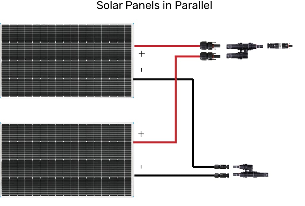
We should multiply Isc by a safety factor of 56% to obtain the fuse rating of 15.6A (10 x 1.56).
- Total Volts: V1 = V2 = 20V
- Fuse rating = Parallel Isc x Safety Factor (1.56) = (5A + 5A) x 1.56 = 15.6A
Series-Parallel Connection
If the panels are connected in series-parallel, both the amperage and voltage of each panel is added up. When selecting fuses or circuit breakers, you need to check the rated short circuit current (Isc) value for the panel you are using. The Isc is the maximum current that the solar panel can produce under any circumstances, and it determines the size of a fuse or circuit breaker for a solar panel as described in the formula below:
| Solar Panels in Series-Parallel | |
|---|---|
| System Voltage* | V = V1 + V2 + ... + Vn |
| Short Circuit Current (Isc)* | Isc = I1 + I2 + ... + In |
| Rated Current of a Fuse or a Circuit Breaker | Isc of Solar Panel x 1.56 |
*In the formula, V and I represent the system voltage and short circuit current of the solar panel respectively, and 1, 2, or n represents the solar panel number respectively. For details about solar panels in series, parallel, and series-parallel, see A Guide Between Series and Parallel Connections.
Example
If you have four 100W panels connected in series-parallel (each two in series and then in parallel), each producing 20 volts and the rated short circuit current (Isc) is 5 amps, the total output would be 40 volts at a short circuit current of 10 amps.
We should multiply Isc by a safety factor of 56% to obtain the fuse rating of 15.6A (10 x 1.56).

- Total Volts: V1 + V2 = 20V + 20V = 40V**
- Fuse rating = Series-Parallel Isc x Safety Factor (1.56) = (5A + 5A) x 1.25 = 15.6A
**V1 and V2 represents Solar Panel Group 1 and Solar Panel Group 2 respectively.
Renogy Recommended Solar Panel Fuse
| Fuse Model | Appearance | Features |
|---|---|---|
|
Solar Connector Waterproof In-Line Fuse Holder w/ Fuse (SKU: RNG-CNCT-FUSE) |
 |
|
Between A Charge Controller and A Battery
To determine the size of the fuse between a charge controller and a battery, simply match the amps rating (or rated charge current) on the charge controller. To ensure your safety, we recommend a safety margin of 25%, resulting in 1.25 times of the rated charge current of the charge controller.
Rated Current of a Fuse or a Circuit Breaker = Rated Charge Current of the Charge Controller x 1.25
For example, if you have a 40A charge controller, we recommend using a 50A fuse between the controller and battery. This will help protect your system if you decide to connect the maximum power to the controller. In addition, it is mindful to use appropriate wiring that can also support the maximum continuous amps for this rating as well for further safety.
Between A Battery and An Inverter or An Inverter Charger
The last fuse would be between your inverter and the battery. Proper wiring size and fuse sizing is critical for inverter application, given their high amp draw nature. A fuse size recommendation is usually stated in the manual and most inverters already have built in fuses/breakers. However, it is always good practice to add more overcurrent protection. The rule of thumb that we use here would be the inverter rating divided by the battery voltage. This value is then multiplied by a safety factor.
Fuse Rating = Inverter Watts/Battery Rated Voltage/Peak Inverter Conversion Efficiency x 1.25
Example
Let’s consider Renogy 1000W Pure Sine Wave Inverter with a 90% peak efficient that is connected to a 12V battery. You want to divide the Inverter Watts by the Battery Voltage AND ALSO the efficiency rating of the inverter.
Fuse Recommended = 1000W/12V/0.90 x 1.25 = 115 Amp or close
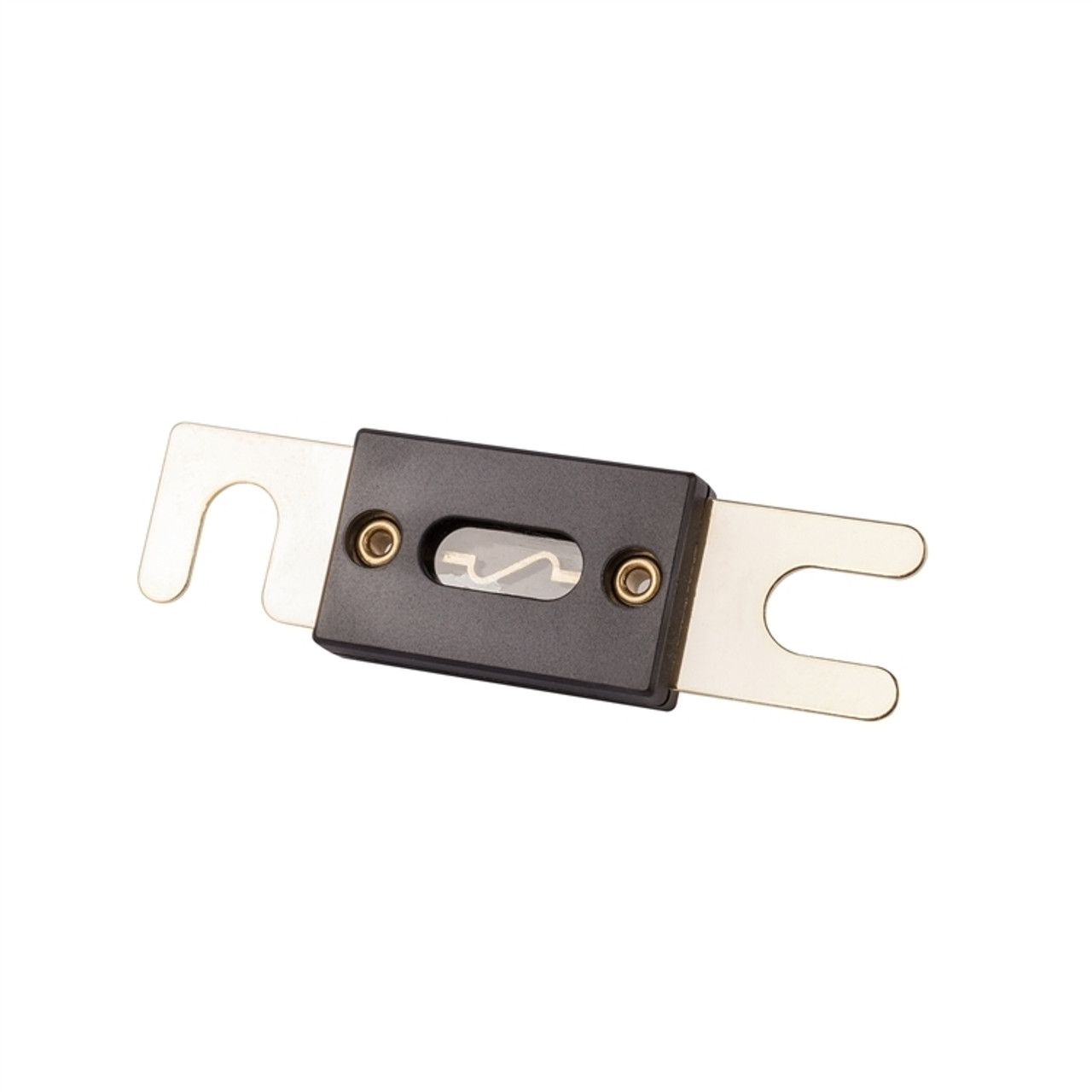
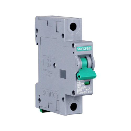
Renogy provides the following fuse and circuit breaker that are applicable between a charge controller or an inverter and a battery.
| Fuse Model | Appearance | Features |
|---|---|---|
|
(SKU: RNG-ANL-FUSE) |
 |
|
|
1P DC Miniature Circuit Breaker (SKU: SUNDCCB10MN1P) |
 |
|
Size Fuse Wires
We can consider the nominal battery voltage (12V) to be the minimum continuous amps, as the value can increase when applying a low battery voltage and a safety factor. Therefore, when selecting which wire gauge to connect to the inverter it is also important to consider the continuous amps. The chart below shows the ampacity for wires in a conduit per NEC Table.
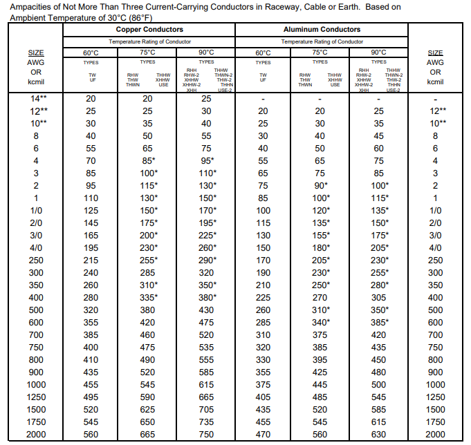
Considering the NEC for the 3 situations:
- Between solar panels and a charge controller
If you have 2 panels in parallel and expecting 10A to 12A from solar panels to a controller, a 14 AWG copper wire with 90°C insulation is rated for 25A and would work in this application as you would want to oversize for protection. - Between a charge controller and a battery
If you are connecting and expecting 40A from a controller to a battery, a 8 AWG copper wire with 90°C insulation is rated for 55A and would work in this application as you would want to oversize for protection. - Between a battery and an inverter
If you are connecting and expecting about 92A from a battery to an inverter, a 4 AWG copper wire with 90°C insulation is rated for 95A and would work in this application as you would want to oversize for protection.
NOTE:
This is a brief introduction and summary for fusing selecting wire gauge for your system. There are other factors such as cable length, voltage drop, and fuse/breaker types that could be considered depending on the application. For details on how to size a wire in a power system, see Sizing Wires for PV Systems.


